Introduction
Ever wondered how robots can follow a line so precisely? Whether it’s a toy robot or an industrial machine, line-following robots use a combination of sensors and control algorithms to stay on track. In this tutorial, we’ll build a line-following robot using an Arduino microcontroller and a QRT sensor array, and we’ll employ PID (Proportional-Integral-Derivative) control to ensure smooth and accurate movement.
Objectives
By the end of this tutorial, you’ll:
- Understand the basics of PID control.
- Learn how to interface a QRT sensor array with an Arduino.
- Implement a line-following algorithm using PID control.
Are you ready to dive into the world of robotics? Let’s get started!
Prerequisites
Before we begin, ensure you have a basic understanding of:
- Arduino programming.
- Electronic components and circuit design.
- PID control concepts.
If you’re new to any of these topics, don’t worry! This tutorial will guide you through each step.
Materials and Components
Hardware
- Arduino Uno: The brain of our robot.
- QRT sensor array: To detect the line.
- Motor driver (L298N or similar): To control the motors.
- DC motors with wheels: For movement.
- Chassis: The body of the robot.
- Power supply: Batteries or a power bank.
- Connecting wires and jumper cables.
- Breadboard and resistors (if needed).
Software
- Arduino IDE: To program the Arduino.
- Libraries: For sensor and motor control.
Section 1: Assembling the Robot
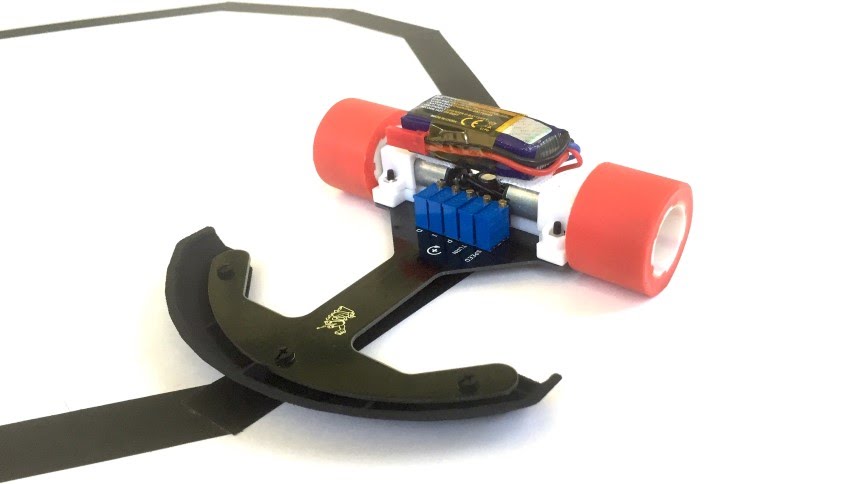
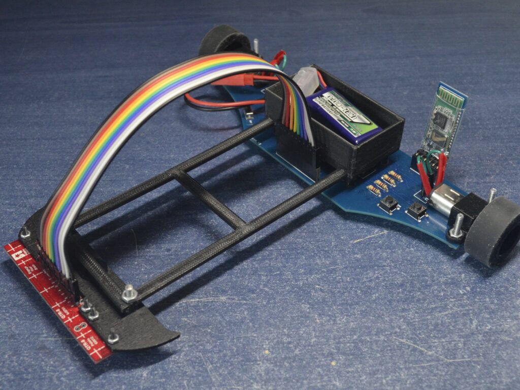
Building the Chassis
Start by assembling the chassis. This will be the foundation of your robot. Attach the DC motors and wheels to the chassis. Ensure they are securely fixed so they don’t wobble during movement.
Connecting the Motor Driver
Next, wire the motor driver to the motors. Connect the motor driver’s input pins to the Arduino’s digital pins. For example, IN1, IN2, IN3, and IN4 on the motor driver can be connected to pins 8, 9, 10, and 11 on the Arduino.
Mounting the QRT Sensor Array
Attach the QRT sensor array to the front of the robot. Make sure it’s close enough to the ground to detect the line but not so close that it touches the floor. Connect the sensor array to the Arduino using the appropriate pins (e.g., A0 to A5 for analog inputs).
Section 2: Wiring the Components
Power Supply
Connect your power supply to the Arduino and motor driver. Ensure you’re using the correct voltage to avoid damaging any components.
Wiring Diagram
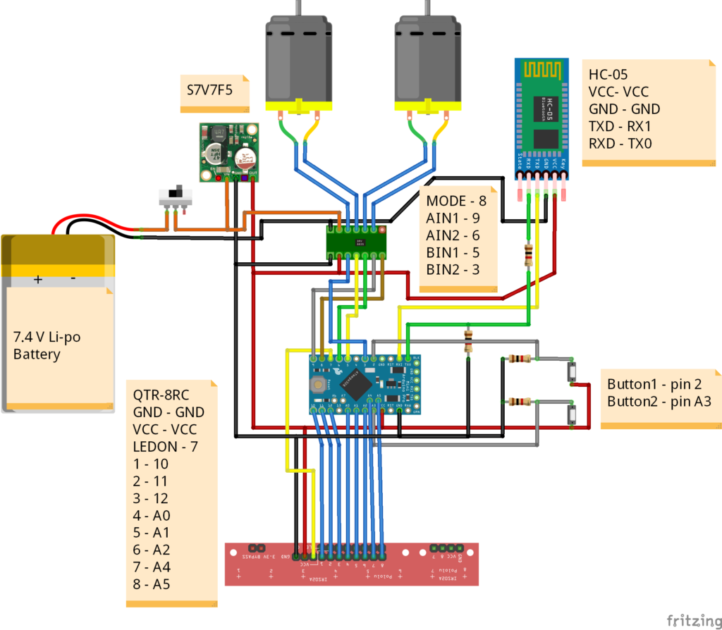
Here’s a simplified wiring diagram to help you out:
- Motor Driver to Arduino:
- IN1 -> Pin 8
- IN2 -> Pin 9
- IN3 -> Pin 10
- IN4 -> Pin 11
- QRT Sensor Array to Arduino:
- Sensor outputs -> A0 to A5
- Power Connections:
- 5V and GND from Arduino to sensor array.
- Motor driver power inputs to battery.
Section 3: Understanding PID Control
Introduction to PID Control
PID control stands for Proportional, Integral, and Derivative control. It’s a feedback control loop mechanism widely used in industrial control systems.
- Proportional (P): Reacts to the current error.
- Integral (I): Reacts to the accumulation of past errors.
- Derivative (D): Reacts to the rate of change of the error.
Why use PID control? It helps our robot correct its path smoothly and quickly. Without PID, the robot might oscillate around the line or react too slowly.
Tuning PID Parameters
Tuning involves finding the right balance between P, I, and D values. This is usually done through trial and error:
- Start with a small P value and gradually increase until the robot follows the line with minimal oscillation.
- Add a small I value to reduce steady-state error.
- Introduce a D value to dampen the oscillations.
Section 4: Programming the Arduino
Setting Up the Arduino IDE
Download and install the Arduino IDE from the official website. Open the IDE and create a new project.
Reading Sensor Values
First, write code to read values from the QRT sensor array. This will help us determine the robot’s position relative to the line.
int sensorValues[5]; // Array to hold sensor readings

void setup() {
  Serial.begin(9600);
  for (int i = 0; i < 5; i++) {
    pinMode(A0 + i, INPUT);
  }
}

void loop() {
  for (int i = 0; i < 5; i++) {
    sensorValues[i] = analogRead(A0 + i);
  }
  // Print sensor values for debugging
  for (int i = 0; i < 5; i++) {
    Serial.print(sensorValues[i]);
    Serial.print("\t");
  }
  Serial.println();
  delay(100);
}
Motor Control
Next, write the code to control the motor driver. This includes basic movement commands like forward, left, and right.
void setup() {
  // Set motor driver pins as outputs
  for (int i = 8; i <= 11; i++) {
    pinMode(i, OUTPUT);
  }
}

void forward() {
  digitalWrite(8, HIGH);
  digitalWrite(9, LOW);
  digitalWrite(10, HIGH);
  digitalWrite(11, LOW);
}

void stop() {
  for (int i = 8; i <= 11; i++) {
    digitalWrite(i, LOW);
  }
}

void loop() {
  forward();
  delay(1000);
  stop();
  delay(1000);
}
Implementing PID Control
Combine sensor readings and motor control into a PID control loop.
int lastError = 0;
int integral = 0;

void loop() {
  int position = readSensors();
  int error = position - 2500; // Assuming 2500 is the center

  // PID calculations
  int P = error;
  integral += error;
  int I = integral;
  int D = error - lastError;

  int correction = Kp * P + Ki * I + Kd * D;

  // Adjust motor speeds based on correction
  int leftSpeed = baseSpeed - correction;
  int rightSpeed = baseSpeed + correction;

  setMotorSpeed(leftSpeed, rightSpeed);

  lastError = error;
  delay(50);
}
In the code above, readSensors() calculates the position based on sensor values, and setMotorSpeed() adjusts motor speeds.
Section 5: Testing and Calibration
Initial Testing
Upload your code to the Arduino and place the robot on a line. Does it follow the line? If not, here are some common issues:
- Sensors not reading correctly.
- Incorrect motor wiring.
- PID parameters need tuning.
Fine-Tuning PID Parameters
Adjust the PID values for optimal performance. Start with the P value, then fine-tune I and D values. Test on different tracks to ensure robustness.
Section 6: Advanced Improvements
Speed Optimization
To improve the speed, you can:
- Increase the base speed in the code.
- Use faster motors.
- Optimize the PID loop for faster response.
Handling Complex Tracks
For sharp turns and intersections, modify the code to handle abrupt changes in sensor readings. You might need to add logic to slow down at turns.
Adding Features
Consider adding:
- Ultrasonic Sensors: For obstacle detection.
- Bluetooth/Wi-Fi Module: For remote control.
- LED Indicators: To show robot status.
Conclusion
You’ve now built a PID controlled line-following robot! We covered everything from assembling the robot, wiring the components, understanding PID control, programming the Arduino, to testing and fine-tuning.
Remember, robotics is all about experimentation and learning from failures. What improvements will you make next?
Appendices
Full Code Listing
Complete code used in this tutorial:
/*
 * File name: PID_LF_example
 *
 * Hardware requirements:  an Arduino Pro Mini
 *                        a QTR-8RC Reflectance Sensor Array
  *                        a DRV8835 Dual Motor Driver Carrier
 *
  * Description: The basic PID control system implemented with
 *              the  line follower with the specified hardware.
 *              The robot can follow  a black line on a white surface
 *              (or vice versa).
 * Related  Document: See the written documentation or the LF video from
 *                   Bot  Reboot.
 *
 * Author: Bot Reboot
 */

#include  <QTRSensors.h> //Make sure to install the library

/*************************************************************************
*  Sensor Array object initialisation
*************************************************************************/
QTRSensors  qtr;
const uint8_t SensorCount = 8;
uint16_t sensorValues[SensorCount];

/*************************************************************************
*  PID control system variables
*************************************************************************/
float  Kp = 0; //related to the proportional control term;
              //change the  value by trial-and-error (ex: 0.07).
float Ki = 0; //related to the integral  control term;
              //change the value by trial-and-error (ex: 0.0008).
float  Kd = 0; //related to the derivative control term;
              //change the  value by trial-and-error (ex: 0.6).
int P;
int I;
int D;

/*************************************************************************
*  Global variables
*************************************************************************/
int  lastError = 0;
boolean onoff = false;

/*************************************************************************
*  Motor speed variables (choose between 0 - no speed, and 255 - maximum speed)
*************************************************************************/
const  uint8_t maxspeeda = 150;
const uint8_t maxspeedb = 150;
const uint8_t basespeeda  = 100;
const uint8_t basespeedb = 100;

/*************************************************************************
*  DRV8835 GPIO pins declaration
*************************************************************************/
int  mode = 8;
int aphase = 9;
int aenbl = 6;
int bphase = 5;
int benbl =  3;

/*************************************************************************
*  Buttons pins declaration
*************************************************************************/
int  buttoncalibrate = 17; //or pin A3
int buttonstart = 2;

/*************************************************************************
*  Function Name: setup
**************************************************************************
*  Summary:
* This is the setup function for the Arduino board. It first sets up  the
* pins for the sensor array and the motor driver. Then the user needs to
* slide the sensors across the line for 10 seconds as they need to be
*  calibrated.
*
* Parameters:
*  none
*
* Returns:
*  none
*************************************************************************/
void  setup() {
  qtr.setTypeRC();
  qtr.setSensorPins((const uint8_t[]){10, 11,  12, 14, 15, 16, 18, 19}, SensorCount);
  qtr.setEmitterPin(7);//LEDON PIN

  pinMode(mode, OUTPUT);
  pinMode(aphase, OUTPUT);
  pinMode(aenbl, OUTPUT);
  pinMode(bphase, OUTPUT);
  pinMode(benbl, OUTPUT);
  digitalWrite(mode,  HIGH); //one of the two control interfaces
                            //(simplified  drive/brake operation)
  delay(500);
  pinMode(LED_BUILTIN, OUTPUT);

  boolean Ok = false;
  while (Ok == false) { // the main function won't start  until the robot is calibrated
    if(digitalRead(buttoncalibrate) == HIGH) {
      calibration(); //calibrate the robot for 10 seconds
      Ok = true;
    }
  }
  forward_brake(0, 0); //stop the motors
}

/*************************************************************************
*  Function Name: calibration
**************************************************************************
*  Summary:
* This is the calibration function for the QTR-8RC Reflectance Sensor  Array.
* The function calls the method 'qtr.calibrate()' offered by the imported
* library. For approx. 10 seconds, each of the 8 sensors will calibrate with
*  readings from the track.
*
* Parameters:
*  none
*
* Returns:
*  none
*************************************************************************/
void  calibration() {
  digitalWrite(LED_BUILTIN, HIGH);
  for (uint16_t i = 0;  i < 400; i++)
  {
    qtr.calibrate();
  }
  digitalWrite(LED_BUILTIN,  LOW);
}

/*************************************************************************
*  Function Name: loop
**************************************************************************
*  Summary:
* This is the main function of this application. When the start button  is
* pressed, the robot will toggle between following the track and stopping.
*  When following the track, the function calls the PID control method.
*
*  Parameters:
*  none
*
* Returns:
*  none
*************************************************************************/
void  loop() {
  if(digitalRead(buttonstart) == HIGH) {
    onoff =! onoff;
    if(onoff = true) {
      delay(1000);//a delay when the robot starts
    }
    else {
      delay(50);
    }
  }
  if (onoff == true)  {
    PID_control();
  }
  else {
    forward_brake(0,0); //stop the  motors
  }
}

/*************************************************************************
*  Function Name: forward_brake
**************************************************************************
*  Summary:
* This is the control interface function of the motor driver. As shown  in
* the Pololu's documentation of the DRV8835 motor driver, when the MODE is
* equal to 1 (the pin is set to output HIGH), the robot will go forward at
*  the given speed specified by the parameters. The phase pins control the
* direction  of the spin, and the enbl pins control the speed of the motor.
*
* A warning  though, depending on the wiring, you might need to change the
* aphase and bphase  from LOW to HIGH, in order for the robot to spin forward.
*
* Parameters:
*  int posa: int value from 0 to 255; controls the speed of the motor A.
*  int  posb: int value from 0 to 255; controls the speed of the motor B.
*
* Returns:
*  none
*************************************************************************/
void  forward_brake(int posa, int posb) {
  //set the appropriate values for aphase  and bphase so that the robot goes straight
  digitalWrite(aphase, LOW);
  digitalWrite(bphase,  LOW);
  analogWrite(aenbl, posa);
  analogWrite(benbl, posb);
}

/*************************************************************************
*  Function Name: PID_control
**************************************************************************
*  Summary:
* This is the function of the PID control system. The distinguishing
* feature of the PID controller is the ability to use the three control
*  terms of proportional, integral and derivative influence on the controller
*  output to apply accurate and optimal control. This correction is applied to
*  the speed of the motors, which should be in range of the interval [0, max_speed],
*  max_speed <= 255.
*
* Parameters:
* none
*
* Returns:
*  none
*************************************************************************/
void  PID_control() {
  uint16_t position = qtr.readLineBlack(sensorValues); //read  the current position
  int error = 3500 - position; //3500 is the ideal position  (the centre)

  P = error;
  I = I + error;
  D = error - lastError;
  lastError = error;
  int motorspeed = P*Kp + I*Ki + D*Kd; //calculate the correction
                                       //needed to be applied to the speed

  int motorspeeda = basespeeda + motorspeed;
  int motorspeedb = basespeedb -  motorspeed;

  if (motorspeeda > maxspeeda) {
    motorspeeda = maxspeeda;
  }
  if (motorspeedb > maxspeedb) {
    motorspeedb = maxspeedb;
  }
  if (motorspeeda < 0) {
    motorspeeda = 0;
  }
  if (motorspeedb < 0)  {
    motorspeedb = 0;
  }
  forward_brake(motorspeeda, motorspeedb);
}
Troubleshooting Guide
Issue: Robot doesn’t move. Solution: Check motor wiring and power supply.
Issue: Robot wobbles around the line. Solution: Adjust the PID parameters, starting with the P value.