Arduino has emerged as one of the most popular platforms for electronics prototyping and DIY projects. Whether you’re an absolute beginner or an experienced hobbyist, Arduino offers a versatile and accessible way to bring your ideas to life. In this article, we’ll walk you through the basics of Arduino programming using the Arduino UNO, one of the most widely used Arduino boards.
What is Arduino and Why Use It?
Arduino is an open-source electronics platform based on easy-to-use hardware and software. It consists of a physical programmable circuit board (often referred to as a microcontroller) and a development environment for writing, compiling, and uploading code to the board. Arduino is used for building interactive objects or environments, such as blinking LEDs, robots, sensors, and more, making it a valuable tool for hobbyists, educators, and professionals alike.
Basic Types of Arduino
Arduino offers a range of boards suited for different applications and levels of expertise. Some common types include:
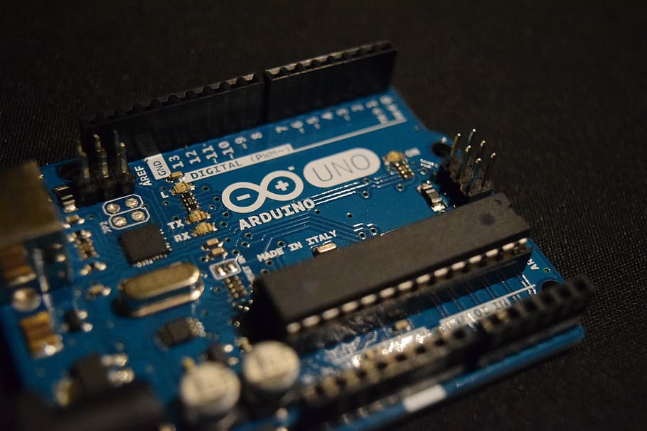
Arduino UNO: This is one of the most popular and widely used Arduino boards. It features 14 digital input/output pins, 6 analog inputs, a USB connection, a power jack, and more.
Arduino Nano: A compact and breadboard-friendly board with similar capabilities to the UNO but in a smaller form factor.
Arduino Mega: Ideal for projects that require a large number of I/O pins and more memory, the Mega offers 54 digital I/O pins and 16 analog inputs.
For the purpose of this guide, we’ll focus on the Arduino UNO.
1 – Getting Started: Blinking an LED
First we are going to start with our Online tool : https://wokwi.com/projects/new/arduino-uno
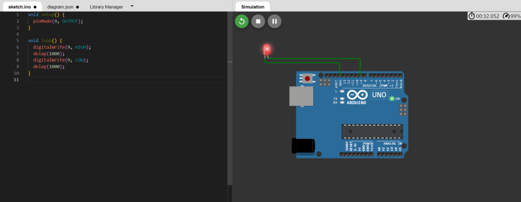
Let’s make our first LED blinking circuit online like above
- Open the Online Tool: Navigate to the provided link for the online circuit design tool.
- Select Components: Choose the components needed for the circuit, including an Arduino UNO board, an LED, a resistor (if necessary), and jumper wires.
- Connect Components: Use the tool’s interface to connect the components as per the circuit diagram. Typically, you’ll connect one leg of the LED to a digital pin on the Arduino, and the other leg to ground via a resistor.
- Verify Circuit: Double-check the connections to ensure they match the intended circuit diagram.
- Simulate Circuit: Some online tools allow you to simulate the circuit to see how it behaves before implementing it in hardware.
- Save or Export: Save the circuit design for reference or export it as an image to include in your documentation.
2- Software installation
Here is the link to complete software and drivers CH340 for arduino:
https://drive.google.com/drive/folders/1tuTld95ltzNGNt9v_KtexJx2X_C40s1r?usp=drive_link
Install the software and drivers then build that same circuit on hardware as below with same code:
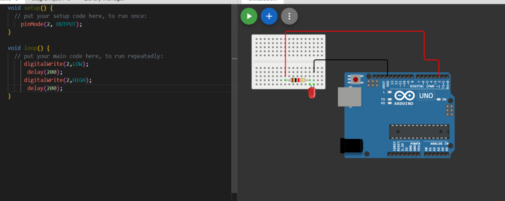
// LED blinking Code:

void setup() {
  // put your setup code here, to run once:
    pinMode(2, OUTPUT);
}

void loop() {
  // put your main code here, to run repeatedly:
     digitalWrite(2,LOW);
      delay(200);
     digitalWrite(2,HIGH);
      delay(200);
}
Now that the software is set up, let’s write a simple program to blink an LED connected to pin 9 of the Arduino UNO:
- Open Arduino IDE: Launch the Arduino IDE on your computer.
- Write Code: Copy and paste the provided code into the Arduino IDE’s code editor.
- Upload Code: Click the upload button (right arrow icon) to compile and upload the code to the Arduino board.
- Observe LED: Once uploaded, observe the LED connected to pin 9 blinking on and off at one-second intervals.
3- Serial Communication using Arduino
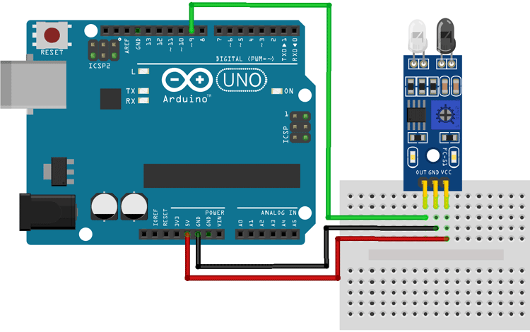
Serial communication allows the Arduino board to communicate with a computer or other devices. Here’s how to incorporate it with an IR sensor:
- Connect IR Sensor: Wire the IR sensor to the Arduino board, ensuring power, ground, and signal connections are correctly made.
- Open Serial Monitor: In the Arduino IDE, navigate to Tools > Serial Monitor to open the serial monitor window.
- Read Sensor Data: Write a program to read data from the IR sensor and print it to the serial monitor. This allows you to observe the sensor’s output in real-time.
Serial communication Syntax:
Serial.begin(9600)
Serial.print("RoboTube")
4- IR Sensor Control
Now, let’s use the data from the IR sensor to control the LED on pin 9:
- Modify LED Code: Adapt the blinking LED program to include logic based on the sensor input. For example, if the sensor detects an object, turn on the LED; otherwise, turn it off.
- Upload Modified Code: Upload the modified code to the Arduino board and observe the LED behavior based on the IR sensor input.
void setup() {
  pinMode(2,INPUT);
  pinMode(9,OUTPUT);
  Serial.begin(9600);
}

void loop() {
  if(digitalRead(2)) digitalWrite(9,LOW);
  else digitalWrite(9,HIGH);
}
5- Motor Control with L293D Shield
To control motors, especially larger ones, you’ll often need a motor driver shield like the L293D. Here’s how to integrate it with the Arduino:
- Install Library: Download and install the Adafruit motor shield library from the Arduino Library Manager.
- Wire Motor Shield: Connect the L293D motor shield to the Arduino board according to the manufacturer’s instructions.
- Write Motor Control Code: Write a program to control a motor connected to the motor shield, specifying the direction and speed.
Syntax for using Adafruit Motor Shield Library

#include <AFMotor.h>

  AF_DCMotor motor(4);

  motor.setSpeed(200);

  motor.run(RELEASE);

  motor.run(FORWARD);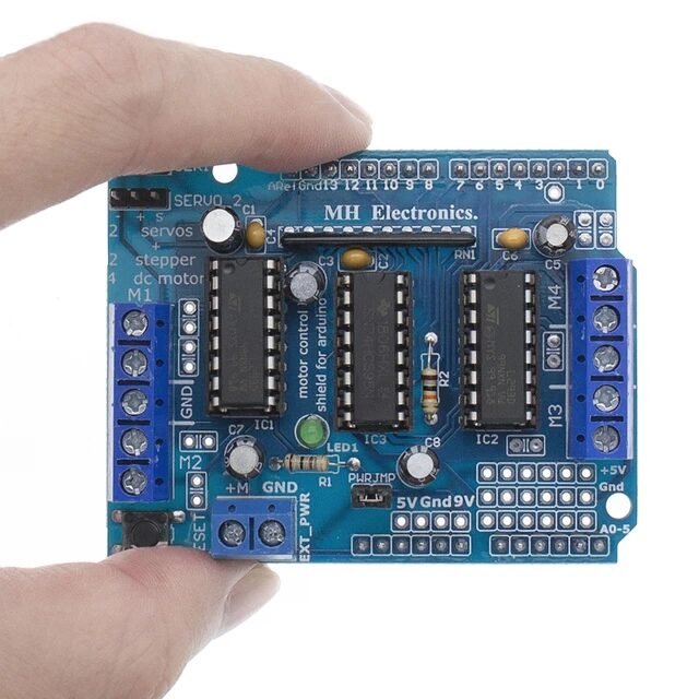
#include <AFMotor.h>
AF_DCMotor motor(1);

void setup() {
   motor.setSpeed(200);
   motor.run(RELEASE);
}

void loop() {


  motor.run(FORWARD);
 delay(1000);
 motor.run(RELEASE);
 delay(1000);
 motor.run(BACKWARD);
 delay(1000);
 motor.run(RELEASE);
 delay(1000);

}
What is a Line Following Robot?
A line following robot is an autonomous robotic vehicle designed to follow a predetermined path marked by a contrasting line on the surface. These robots typically employ sensors to detect the line and make course corrections accordingly, allowing them to traverse intricate paths with precision. Despite their seemingly straightforward concept, line following robots embody fundamental principles of robotics, including sensor integration, decision-making algorithms, and motor control.
How Do They Work?
Line following robots rely on a combination of sensors, actuators, and control algorithms to navigate along a designated path. The basic operational principle involves the following steps:
- Sensor Detection: The robot is equipped with one or more sensors, such as infrared (IR) sensors or reflective optical sensors, positioned close to the surface. These sensors emit light and detect variations in reflectivity caused by the line. When the sensor detects the line, it generates a signal indicating its position relative to the line.
- Data Processing: The signals from the sensors are processed by the robot’s microcontroller or onboard computer. Algorithms are employed to interpret the sensor data and determine the robot’s position relative to the line. Based on this information, the robot decides whether it needs to adjust its course to stay on the line.
- Motor Control: The microcontroller sends commands to the robot’s motors to adjust its direction of motion. By selectively controlling the speed and direction of the motors, the robot can turn or correct its trajectory to stay aligned with the line.
- Feedback Loop: The process repeats continuously as the robot moves along the path. The sensors continuously provide feedback to the microcontroller, allowing the robot to make real-time adjustments and maintain its course.
Educational Significance
Line following robots hold significant educational value, particularly in academic settings and robotics workshops. Here’s why they are often taught in schools:
- Introduction to Robotics: Line following robots provide an accessible entry point into the field of robotics, allowing students to explore fundamental concepts such as sensor integration, feedback control, and algorithm design.
- Hands-On Learning: Building and programming a line following robot offers a hands-on learning experience that engages students in practical problem-solving and experimentation.
- Interdisciplinary Learning: Line following robots integrate concepts from various disciplines, including electronics, programming, and mechanical engineering, fostering interdisciplinary learning and skill development.
- Problem-Based Learning: Designing and optimizing a line following robot involves iterative problem-solving, encouraging students to apply critical thinking and creativity to overcome challenges.
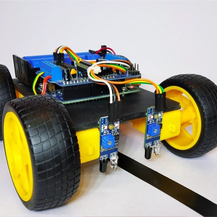
Circuit Explanation with Arduino, L293D Shield, Motors, and IR Sensors
To illustrate the construction of a line following robot, let’s outline a simple circuit using Arduino, an L293D motor shield, two motors, and two IR sensors:
- Arduino UNO: The Arduino UNO serves as the brain of the robot, responsible for processing sensor data and controlling motor movements.
- L293D Motor Shield: The L293D motor shield provides motor drivers for driving the robot’s motors, allowing precise control over their speed and direction.
- Motors: Two DC motors are connected to the motor shield, one for each wheel of the robot. These motors drive the movement of the robot.
- IR Sensors: Two IR sensors are positioned at the front of the robot, facing downwards to detect the line on the surface.
Circuit Connections:
- Motor Connections: Connect the two DC motors to the motor shield outputs, ensuring proper polarity and connection.
- IR Sensor Connections: Wire the IR sensors to digital input pins on the Arduino board, ensuring each sensor’s output is connected to a separate pin.
- Power Supply: Provide power to the Arduino board and the motor shield, ensuring sufficient voltage and current capacity for the motors.
Operational Flow:
- Sensor Detection: The IR sensors continuously monitor the surface beneath the robot, detecting the presence of the line.
- Data Processing: The Arduino reads the sensor data and determines the robot’s position relative to the line.
- Motor Control: Based on the sensor inputs, the Arduino sends commands to the motor shield to adjust the motors’ speed and direction, keeping the robot aligned with the line.
- Feedback Loop: The process repeats iteratively as the robot moves along the path, making real-time adjustments to maintain course.
By constructing and programming a line following robot, students gain practical experience in electronics, programming, and robotics, laying the foundation for further exploration and innovation in the field.
You Made it here !!
By following these steps, you’ll gain hands-on experience with Arduino programming and be well-prepared to explore more complex projects and applications.
