A line following robot is usually a simple 2 or 4 wheeled toy car that is programmed to follow a line under it. These robots may be used to in various industrial and domestic applications such as to carry goods, floor cleaning, delivery services and transportation. We call it robot because it has ability to take decision on its own according to its path or line.
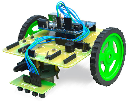
To design a simple line following robot, we need following components:
- 2 x motors (DC Geared)
- 2 x Wheels
- 1 x Robot chassis or body (simple acrylic sheet)
- 1 x battery (9-12V)
- 1 x Switch
- 1 x Motor driver (l298n)
- 1 x Arduino (UNO or Nano)
- Minimum 3 x Analog IR Sensors
- Some wires
- And Some patience
Now to start with
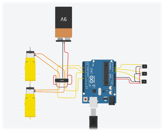
- First assemble both of your wheels and motors and attach them properly with your body, place the battery and connect switch with it.
- Now from Power and Ground of battery connect your motor driver, check if it is working or not by turning on and off (LED indicator is included in motor drivers usually)
- Now connect GND and 5V of Arduino with motor driver, now while checking you can see if Arduino is turning on and off as well or not.
- Connect 4 PWM wires of Motor driver with Arduino. We use 3,5,6 and pin 9 Usually (Digital)
- Now connect both motors with Motor driver as well.
- After that, take your IR sensors, they usually have 3 pins, 5V, GND and Vout , connect 5V and GND with Arduino or motor driver relevant pins, first connect them together with each other than take 1 wire to driver or Arduino.
- Now connect Vout of each sensor with Arduino as A1, A2 and A3.
That’s it for wiring, its time to program it.
To start with programming, we will perform it in 2 stages.
First one will be calibration. To calibrate your motors, you simply have to provide voltages to each pwm pin and see which one is forward and backward, left and right.
Here is the code for motors calibration.
 /*

 Calibration code

 */

 void setup() {
     pinMode(3,OUTPUT);
     pinMode(5,OUTPUT);
     pinMode(6,OUTPUT);
     pinMode(9,OUTPUT);
 }

 void loop() {
     //Section1
     analogWrite(3,255);
     analogWrite(5,0);
     analogWrite(6,0);
     analogWrite(9,0);

     //Section2
     // analogWrite(3,0);
     // analogWrite(5,255);
     // analogWrite(6,0);
     // analogWrite(9,0);

     //Section3
     // analogWrite(3,0);
     // analogWrite(5,0);
     // analogWrite(6,255);
     // analogWrite(9,0);

     //Section4
     // analogWrite(3,0);
     // analogWrite(5,0);
     // analogWrite(6,0);
     // analogWrite(9,255);


 }
The loop part of this code contains 4 sections. 3 of them are commented and 1 is active, upload this code, see which motor is running in which direction. You can write them down as
Motor left forward,
Motor right forward,
Motor left backward,
Motor right backward.
Then comment the section 1 and upload section 2 only, similarly repeat the process with a 4 sections and you will find which pin Is exactly providing PWM to which direction of motor. This process will not take more then 2-3 minutes.
I am writing my pin here for example:
Motor left forward :3,
Motor right forward :5,
Motor left backward :6,
Motor right backward :9.
Now create 4 functions like this:
(remember you will add your own pins config, for forward function add both forward pins from your readings, for backward, add both backward reading pins, for right: left motor will be forward and right will be backward and vice versa for left)
Void forward()
 {
     analogWrite(3,255);
     analogWrite(5,255);
     analogWrite(6,0);
     analogWrite(9,0);
 }
 Void backward
 {
     analogWrite(3,0);
     analogWrite(5,0);
     analogWrite(6,255);
     analogWrite(9,255);
 }

 Void left
 {
     analogWrite(3,255);
     analogWrite(5,0);
     analogWrite(6,0);
     analogWrite(9,255);
 }

 Void right
 {
     analogWrite(3,0);
     analogWrite(5,255);
     analogWrite(6,255);
     analogWrite(9,0);
 }
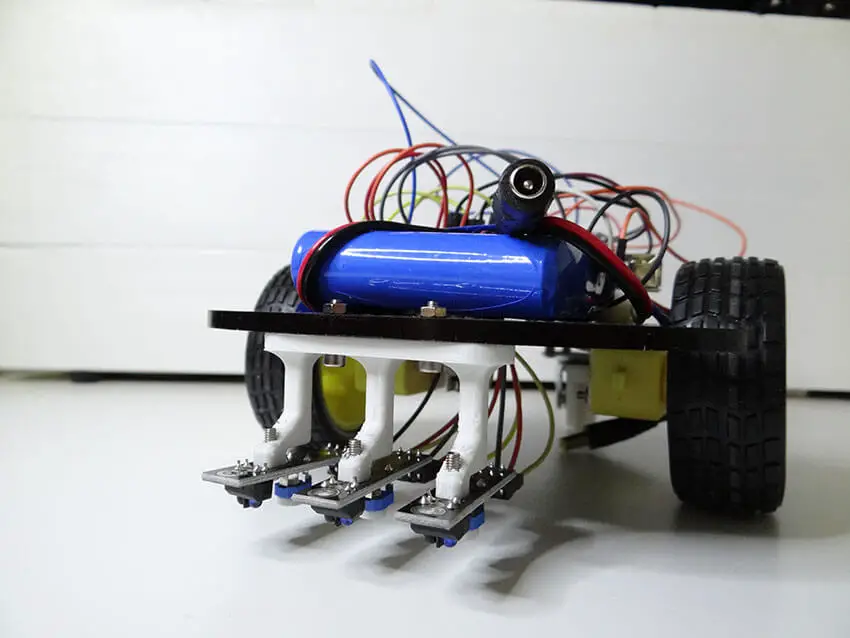
After completing calibration for motors, and now you are clear with their direction and connections as all 4 PWM pins are working, move towards your IR sensors, place them under your robot & upload the following code.
 /*

 Sensors Callibration
 */

 void setup() {

     pinMode(A1,INPUT);
     pinMode(A2,INPUT);
     pinMode(A3,INPUT);
     Serial.begin(9600);

 }

 int s1,s2,s3;
 #define s1val
 #define s2val
 #define s3val

 void loop() {

     s1= analogRead(A1);
     s2= analogRead(A2);
     s3= analogRead(A3);

 Serial.print("s1:  ");
 Serial.print(s1);
 Serial.print("s2:  ");
 Serial.print(s2);
 Serial.print("s3:  ");
 Serial.print(s3);
 Serial.println("");


 }
After uploading your code, open serial monitor and see if baud rate is 9600, you will see some readings. Place your robot on white surface, read those reading and then place it on black surface and read those readings again. You will notice on white your reading will be different and on black they are different (usually greater).
Note down readings for all 3 sensors, find the average of white and black for all 3 sensors, and set it inside your code as s1val , s2val, s3val. You can find these line above loop function.
Now it is time for final code, but before that make sure your s1 s2 and s3 are placed in this order
S1 : left sensor.
S2: middle sensor.
S3: right sensor.
If not, rewire them and with previous code uploaded you can read readings on serial monitor. & here is final code:
 void forward()
 {
     analogWrite(3,255);     analogWrite(5,255);     analogWrite(6,0);     analogWrite(9,0);
 }
 void backward()
 {
     analogWrite(3,0);     analogWrite(5,0);     analogWrite(6,255);     analogWrite(9,255);
 }

 void left()
 {
     analogWrite(3,255);     analogWrite(5,0);     analogWrite(6,0);     analogWrite(9,255);
 }

 void right()
 {
     analogWrite(3,0);     analogWrite(5,255);     analogWrite(6,255);     analogWrite(9,0);
 }


 void setup() {
     pinMode(3,OUTPUT);
     pinMode(5,OUTPUT);
     pinMode(6,OUTPUT);
     pinMode(9,OUTPUT);

     pinMode(A1,INPUT);
     pinMode(A2,INPUT);
     pinMode(A3,INPUT);
     Serial.begin(9600);

 }

 int s1,s2,s3;
 #define s1val 350
 #define s2val 400
 #define s3val 380

 void loop() {

     s1= analogRead(A1);
     s2= analogRead(A2);
     s3= analogRead(A3);

 Serial.print("s1:  ");
 Serial.print(s1);
 Serial.print("s2:  ");
 Serial.print(s2);
 Serial.print("s3:  ");
 Serial.print(s3);
 Serial.println("");


     if (s2 > s2val )
     forward();

     else if (s 3> s3val )
     right();

     else if (s1 > s1val )
     left();

 }