If you want to control the DC motor direction using a relay (direction, not speed), of a 100A DC motor, you simply need 2 x 100A relays.that costs around 20$ instead of a motor controller that will take at least 100$ from your account. So this article is about DC motor control using Relays.
If you want to control a DC motor using microcontroller, the first thing that comes into mind is a motor driver or controller & there are many controllers available in market, for instance if you have small DC motor below 2 Ampere load, you can simply use L293D motor driver to control that motor. But let’s say you have a heavy DC motor that can take 50A as peak current, what are you going to do?

Motor drivers can be expensive, this Sabertooth dual 60A motor driver to control heavy DC motors costs around 200$, and in combat robotics, sometimes this may not be even enough, so if you want to go for simple and cheaper solution and create your own DIY motor controller, you can do that simply with relays as well.
Here we can discuss two important terminologies, i.e H – Bridge and relays, that is all what this article is about:
H-Bridge:
An H bridge is an electrical circuit that allows a voltage to be applied in either direction across a load. H-bridge is basically used to run a DC motor forward and backward for any application, mostly in Robotics etc.
Relays:
Relays are simply electrical switches, they connect and disconnect any path in circuit using a signal, a relay can be small or big, to run different loads.
To trigger a relay we need to provide power to coil, that power again depends on relay model, some are 5V, some are 12V and some requires even more, if coil energize, it turns the relay ON.
By default a relay completes a connection from Input terminal to Normally Connected or (NC) terminal. When coil energizes, it takes connection from NC to NO( Normally Open) terminal. That way we can connect it in circuit to complete any path in circuit when we want to.
To control a motor (direction only not speed) you need two relays. Below is the diagram how you can connect your motors with batteries and relays.
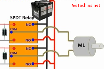
Now as you have seen in the diagram, the system is completely safe, even if you turn both relays on or off, the battery will not be in short circuit.
If both relays are ON or OFF, terminals of motors will be both Negative or Positive of battery and motor will be in idle position.
If Relay 1 triggers, motor turns in one direction and if Relay 2 triggers, motor turns in another. & this is how you can simply control the direction of the motor using relays.
Note that this method will not allow you to control the speed of the motor, and your motor will start directly at full RPM from the battery and stop.
But considering this whole setup even for 60+ A motor will cost you around 10 – 15$, this might work for some applications.
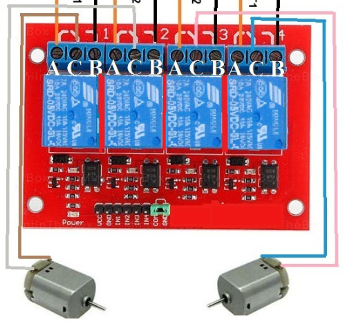
Now here is a diagram if you want to control two motors at a time, you simply need 4 relays.

Remember you have to consider the ratings of the relay as well like you do in a motor driver.
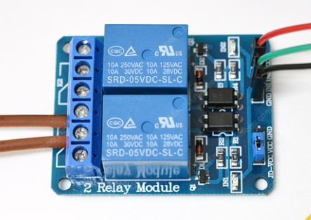
If you use a normal relay module (blue one below) you can directly connect it with an arduino and run approx 4 to 8A of motor load using this.
But if you go beyond that you need to use 12V relays and arduino cannot trigger those relays directly, so you need to have a small motor driver as relay triggers are inductive as well, or octocopters to trigger those relays..
For any question or queries you can contact us.
Keep following Go techies for more 🙂
